When surfing on the BMWLT.com back in the 2005 or so I learned that the HID conversion was the way to go if you wanted more light power on the road. The facelift LT had somewhat better lights than the earlier "charcoal in the bottle" models but I decided to get the HID Xenon's to my LT.
This blog is about some customzing projects of my BMW K 1200 LT motorcycle which I started in 2004, right after I picked up the bike from the dealer.
Wednesday, July 29, 2020
Hella Xenon Micro DE installation
At some point I figured more light for the dark Finnish autumns is needed. Especially when the moose hunting season starts, those huge (and stupid) animals cause a lot of accidents. Most of the fatal for the bikers...
So I found these Hella Xenon Micro DE HID lights that were nice and very powerful and first of all small in size. I had seen people hide their auxiliary lights behind the side panels so I decided to tackle the job as well.
 |
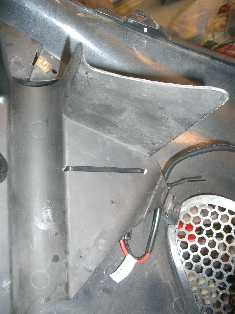
| This shows the final installation. Seen from this angle the lights are not 100 % in vertical position but this does not matter since they are not normally stared from this direction. |
 |
| ...like this. |
 |
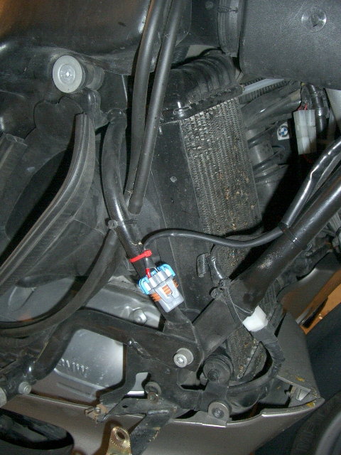
| And here is bike side connector that needs to be disconnected when the side fairing is removed. |
Tuesday, July 28, 2020
How all the farkles were wired?
I started adding things to my bike like many people do. I took power straight from the battery or found some factory connections for the navigator, for instance . After two years I ran into problems. I lost the track of the various cables. Right after you have installed your gadgets you remember that this "blue cable" is for my reversing sensors and this "green one" is for the extra power in the trunk etc.
But after couple of months or a year you don't remember any more what those cables were for.
I used a lot of in-line fuses which are easy and fast to install but can be a pain to access on the road.
So I figured that this is not a long term solution and change has to take place:
- I needed a central power supply that is connected to the battery and the connections to the bike factory electricals must be kept to minimum.
- I needed fuse blocks with at least 15 fuses that can be accessed without pulling the bike apart.
- I start using relays with all my extra gadgets.
- I needed a systematic coding of all my added cables, relays, junction points etc plus proper drawings. Some day the bike might have a second owner (which will not be in any time soon) and nobody will touch the bike with a shorter than 2 meter stick if the changes are not documented.
The power supply:
This main relay is triggered by a push button on my handlebar. I have built a separate "holding circuit" for this main relay (with a help from an other relay) and the pilot current taken from the bike's dash light positive lead. This way I can start the bike with the "factory settings" and it runs normally with the standard lights, turn signals etc and all my extras come on only after I push the button in the handlebar.
 |
| The "extra gadgets on" -button is the second one from the right. (The extra four-way button adjusts the seat up-down and backrest front-back.) |
The fuse blocks:
I figured the fuse blocks needed to be compact in size and preferably use the same mini-size fuses as my facelift LT was also using. I located the fuse blocks from a "Biltema" store but some years later I realized that unfortunately they don't carry these any more.
I currently have three fuse blocks. One for ten fuses in the front under the high beam. One for six fuses under the rider's seat and one for four unswitched (directly from the battery) fuses as well under the seat.
The rear fuse blocks:
The front fuse block:
 |
| This shows the fuse block. The only bad thing is that it is not designed for one common infeed but instead it has the connection tabs on both sides. |
The relays and low amp pilot cables.
Using the relays gave me the advantage of not having to run thick cables all the way to my switches which were starting to add up both in the handlebars as well as on my various dash variations. The pilot current for the relay needs just a very thin cable and those were easy to fit under the handlebar plastic covers etc. I also had to install some relays in the rear part of the bike so I found a nice way to handle the pilot current issue from front to rear...
I started using relays for supplying power to my various add-on things like
- fog lights
- two sets of driving lights (one halogen and one Xenon set)
- extra set of horns
- my seat adjuster
- my Baehr intercoms and bike to bikes radio
- various chargers (cell phones, Ipods, cameras etc)
- rear wiew cameras (all three of them)
etc. etc.
At first I used the standard 12 V car relays which can be obtained at every auto parts store.
I installed the relays under the nose cover and under the seat and trunk.
 |
| This is how the front part of the bike looked before I figured this is a dead end. I run out of space and my cable and relay coding did not work... |
So I decided to start my cable and relay work all over from scratch. Since I already had quite a bit of farkles installed all I had to do was to draw the schematics, decide the cable coding principle, redo all the cables and relays using the mini relays...Easy piece! A nice winter project...
The list of farkles and the schematics:
I used about two months of the winter 2006 to make the schematics. I am not a professional electrician let alone an engineer. I studied closely various schematics principles and to me the Harley-Davidson way of showing the connections was most logical. So I decided to use somewhat similar style in my schematics.
 |
| Here the (1,5 years) old cables and relays were hanging before stripping them out. |
 |
| Most of the stripped old relays here. |
I found the nice new mini relays which occupied a lot less space than the conventional car relays.
 |
| This shows the way the mini relay sockets can easily be joined together. |
 |
| These pictures were taken in 2008 and today this set of 8 relays looks a bit more tight since there are now about 15 of them but I guess this shows the principle... |
- pilot current for the main 80 A relay, taken from the dash light
- pilot current for the auxiliary driving lights, taken from the bike high beam
- pilot current for the trailer isolation relays (turn signals, tail light and brake light). In case something goes wrong with the trailer wiring the isolation relay protects the bike wiring.
In a CAN bus bike some of the above mentioned connections might need to be done a bit otherwise but basically the biggest problem for me with the new K 1600's would be the lack of space for all the extras as well as the radically smaller alternator (840 W -> 580 W) which would most likely be dropped on it's knees with half of my gadgets 😉
If any questions arise please comment on the blog or email directly ari.ignatius@gmail.com
Sunday, July 5, 2020
Organizing and improving the trunk
The trunk of the K 1200 LT has at least three points that seem to be bothering the owners by breaking down.
Those points are the vanity mirror, the strap fixing point and the trunk latch. I have also seen one case where the hinges have been broken but I really don't know how that has happened so it is hard to offer any fixing to that issue.Let's start from the easiest improvement.
The original length of the lid strap is too long. It allows the trunk lid to open too far towards front. If you lose your grip of the lid when opening it and it "falls open" freely, in many cases the fixing point of the strap in the trunk base breaks down. This is because the lid is rather heavy and gains momentum when falling freely open.
 |
| This is the fix! |
 |
| Simply fold the strap again and make another loop so that the strap becomes slightly shorter. If you are not comfortable with needle and thread ask your better half to assist! |
 |
| So that the your lid opens slightly over 90 degrees, enough to stay open by itself but not enough for it to gain enough momentum to break the aluminum lower fixing point. |
Probably the most common failure of the LT trunk is the broken vanity mirror hinge. The mirror is held up by a magnet and if you ride your bike to a bump with empty trunk and there is no support from the luggage, the mirror flips open and quite often breaks the plastic hinge. I broke mine quite early and got a replacement under warranty from the dealer. I figured that these will not be handed over to me on annual basis so something needed to be done.
 |
| I added a stretch band that my wife donated to me and fastened it with boat canvas fasteners. |
 |
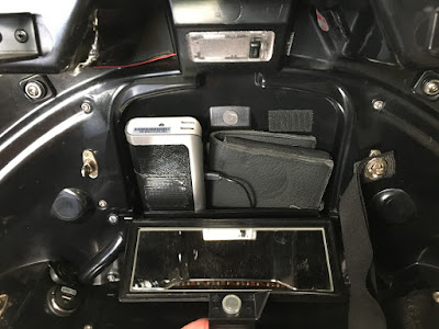
| Here is a better view of the canvas fastener and in the same picture you can see my one 12 V power socket with USB converter. |
 |
| Here is the power bank. In the bottom of the storage box I have one more 12 V outlet with USB charger to keep the power bank charged. |
 |
| Here is the bottom of the storage box with the USB charger. |
In the front wall of the trunk I have a storage space for my first aid kit and the other bag holds the rain cover for my Russell leather seats.
 |
| Like this. Another donation from my wife holds these things in place.... |
 |
| ..together with a thin aluminium L-profile that makes a bottom support for the items. |
The third and most expensive problem with LT trunk is the syndrome of the broken latch. The latch can break when you have slightly overfilled your trunk and then you try to close it by applying extra force to the latch. The material of the latch is some kind of "cheap metal" which is very difficult if not impossible to fix. From the dealer the only fix is to buy the complete trunk lid assembly. Not cheap...
There were two aftermarket kits available for the LT trunk latch. One set for reinforcing the existing mechanism "Fix It Before It Breaks" and the other one to replace the already broken latch. Unfortunately the site LT Trunk Latch.com no longer exists and the manufacturer Evan Guy sold out all his sets already back in 2017.
 |
| These were the parts for the "Fix-It-Before-It-Breaks" set. |
 |
| And this is how they looked after installation. I have had this set since 2009 and it really works. |
However, there is a simple pre-emptive measure that can be done in order to make the latch breakage less probable.
From the factory the locking mechanism has both steel pins and steel hooks to pull down the lid. You can hear the unpleasant scraping sound of the metal against metal when closing it.
What I did already years before purchasing the latch kit above was to add plastic tubes around the pins of the lid lock counter piece.
 |
| The tube that I used was the harder type pneumatic plastic pipe. Inner diameter accorsing to the pin...5 or 6 mm if I remember correct. |
While I was improving my trunk I decided to add some lighting to it. This was simple with a led strip with adhesive.
 |
| I simply stole the 12 volts from the OEM trunk light. |
 |
| This picture shows my rain gear storage which is between the backwards relocated trunk and the passenger seat. The passenger backrest needed to be moved upwards some 20 mm in order to have access to this new space. (See it here) |
Subscribe to:
Comments (Atom)


