Wednesday, June 24, 2020

Monitoring the final drive oil temperature

As all of us BMW K 1200 LT riders know the final drive is something that can create headache. The construction was used already many years before the LT was created and the added weight of this bike added stress to the main bearing of the unit. 
I suppose all of us have heard horror stories of the units failing, typically somewhere on the road and not so often in the garage. 
Even though my bike is of the newer generation when the factory had already paid better attention to the preload setting of the unit during assembly I decided to be safe with my final drive(s). 
At quite early stage, maybe in 2007 or so I was able to purchase two almost new final drives for 400 usd that were taken off from triked LT:s. The other drive went to colleague of mine and I kept the other one (9 miles on it) in my garage as a spare one. 
I took the habit of changing the whole final drive at maximum 50.000 km without any further checking or analysis. I just throw the new one in and change the main bearing to the spare one in the winter. 
In addition to this (no no , I'm not paranoid!) I decided to install an oil temperature gauge as I had some space in  my dash for another gauge.


VDO has a gauge that has a range of 20 - 100 deg C. A gauge with max 80 deg C would be even better since the max normal operating temperature what I have ever experienced seems to be at 65-70  deg C. 

There are two options for installing the sensor. The main thing is to make sure the sensor is not too long so that it would touch anything inside the drive unit.
My first sensor was too long to be installed in the fill plug so I installed it in place of the drain plug. This of course ensures that the sensor is in the oil but my problem was that I never got this sensor to be 100% oil tight. Even if I had a copper washer the sensor / plug was slightly seeping oil which was not very nice.

Later I found a VDO sensor which was short enough to be installed in place of the fill plug. The oil temperature readings are well comparable to the bottom sensor readings so I put the original drain plug in place and changed my fill plug to this.


The sensor needs two wires. One goes to the sensor and one is for grounding. The grounding must make sure it has proper contact with the (in this case) the final drive itself.

At first I used the breathing plug as grounding point but I really did not find a proper way to fix the wire in the plug so I changed the grounding point to the disc brake assembly. At this time unfortunately I don't have a picture of that but if I recall correctly there is the ABS sensor grounding point available and I simply put another ring connector under the same screw.
This final drive oil temperature gauge installation was made in 2008 and so far I have learned that the highest temperatures so far (about 68 deg C) have been when riding on German Autobahns at 130 km/h average speed two up and pulling Uni-Go trailer at + 28 deg C weather. Actually the final drive oil temperature follows very well the engine oil temperatures only at slower pace. This meaning that that engine oil temperature goes up faster than the final drive oil but the in longer ride they both end up to very close readings. The final drive  gauge also shows how efficient cooling water provides. In rainy weather the oil temperature gauge barely moves up regardless of the speed. 

Thursday, June 18, 2020

BakUp backrest and motor adjustment for it

After I had made the rider's seat power height adjuster I got the idea of the backrest adjuster from Bruce Hodges (aka "bruce2000ltc") on the BMWLT.com back in 2008. He was using one of the battery operated screwdrivers to do the adjusting and while searching the right kind of unit I probably mentioned about this on the forum. The next surprise came in mailbox as some weeks later I received a small power screwdriver from Anthony Kay (aka "deputy 5211") who even refused to receive a payment for the unit!
OK, thanks to the help from my American LT colleagues I now had both the idea and components in my hands, time to get things done...

This hint came from Bruce. The original spring that pushes the backrest forward is too strong for the motor adjuster. So it needed to be trimmed to make it weaker.


Here is the actual motor. As it was taken out from it's original housing it was no longer held together by it so I needed some epoxy glue to keep it together. Looks like I also needed to trim the cover a little bit.


Here is the BakUp frame and I used some fiberglass putty to make the new housing for the motor. I applied soft putty in the frame and then pressed the motor in place to make the shape. Motor was covered with Ceran wrap I borrowed from my wife's kitchen so the putty would not stick to it. The allen screw has a piece of a cut allen wrench in it which in turn is the standard size the power screwdrivers use.


Here the motor is in place and it is covered with some shrink tube for moisture protection. The idea is that the motor turns the adjuster screw which determines the angle of the backrest. The piece of allen wrench connecting motor and bolt must be long enough to allow the screw travel up and down since the motor does not move. 


A small challenge was the voltage of the motor, 3,6 V. So I used the battery case and added an old Nokia car charger for charging the batteries. 


For those I found space in the bikes's main electrical box under the gas tank. 


To run the motor in two directions via two push buttons I needed two relays to change the directions. The relays operate with 12 V, and the low voltage is run through the relay pins. The next picture shows the schematics but the text is in Fnnish, sorry...OOPS, now I realized that at some point I had replaced the battery pack with a simple USB 5 V charger. The motor is run only for a max 2 seconds so it can easily tolerate the 1,4 volts overvoltage.  


To adjust the backrest I use the horizontal buttons of the old four way radio band selector. (The vertical buttons are for the seat up/down.) This is and old picture as the upper button set is nowadays on the left handlebar....

Like ths...


Here is the motor hidden under a little larger vinyl cover than the original. 
This adjuster has worked since 2008. I oil the adjuster screw every now and then. That is all it has needed so far.

Saturday, June 13, 2020

Luggage rack tail lights


One time I had the luggage rack removed for some reason and while having it in my hands I realized that why not install some more taillights in it.

At first I drilled the three holes in the rear legs of the luggage rack. The diameter of the holes must of course match the size of the leds.

Then I inserted the leds in the holes and soldered their legs together. These leds were connected in series which means that the shorter leg is connected to the longer leg of the next led.
Since I happen to have a lot of photos of the next phases I just add them here in case you want to copy this.

You must calculate the resistor that is needed on the "longer leg" side of the led system. You will find a lot of instructions by writing on Google search "calculating led resistor values" for instance. The picture above shows how I simply wrapped the resistor leg around the longer leg of the led before adding a drop of solder on it. The shorter leg already has the minus-side of the 12 V wire connected and covered with shrink tube.


Here the led set is being tested in place.


There is plenty of room in this place to apply hot melt glue generously. This keeps the leds in place and also seals them properly. These were installed back in 2007 and they are still working.

In this picture you can see how the power for the leds is brought through the same hole as the factory brake light power. The cable glued with the three hot glue spots is the one taking the power to the other side leds and the cable in the upper part of the photo is the main lead bringing the power from the bike tail lights. In order to fit this cable properly I used Dremel for grinding a proper route in the plastic for the cable.

Like this...

...and this.

After the cable routes are clear inside the rack and the hot glue is applied in the needed places then just screw the rack back together and on top of the trunk lid. Follow the factory brake light cable route and take your new tail light cable along it. You can take the power to the tail lights from various sources but don't forget to use a quick connector between the trunk and the rest of the bike. In case you need to remove the trunk for some reason then this new cable can be disconnected together with the factory trunk connectors. 


Friday, June 12, 2020

Adding oil to rear suspension preload adjuster

Over the years the preload adjustment of the rear spring tends to "get tired". Turning the adjustement wheel tighter does not lift the bike as it used to. The preload adjustment in the stock Showa rear spring is done by hydraulic oil (jack oil) and eventually some of it (if not all) just disappears. In the following I show how to refill it.

A word of warning: I have heard of at least two preload adjusters that have been broken (the threads have been shot) because the adjuster has been turned with the bike loaded or even just sitting normally on ground.  So I advise that you only adjust the preload with the bike on centerstand in order to prevent extra stress to the adjuster wheel.

Put the bike on center stand and turn the adjuster all the way open (counterclockwise). Then release the bolts of the adjuster so that you can hold it in your hand.
When you have the adjuster in your hand, grab it firmly with a vise grip or similar and open the hose connector. Do not loose the copper washers! 

When the hose is disconnected, store it temporarily in uphill position so that it will not accidentally drain out.


Like this....


Make sure the adjustment wheel is turned all the way open (counterclockwise). Then place it on the floor and after this use a thin screwdriver or similar to push the piston all the way down. 


Next use a pipette to fill the chamber above the piston with jack oil. Fill it all the way.
When you have filled the adjuster, reconnect the hose to the adjuster. Remember the copper washers. Try to tighten the connector in the same position as it was so the hose comes out in correct position.

When the adjuster is in place, turning it clockwise (tighter) should the rear spring get slightly longer and thus it should feel a little stiffer as well. However, if the rear spring has already lots of miles behind, this trick will not bring it to back to "as new" condition. This is just a simple "first aid" to those who feel that their bike seems to sit lower than what it used to.

A more permanent fix to improve the LT's suspension is to change both front and rear springs to Öhlins or Wilbers or similar. I went for Öhlins and the bike certainly feels more stable especially in long sweepers

Thursday, June 4, 2020

Making the seat height adjuster

When I received the Russell seat which was made in the frame of and earlier model LT I found the seat height adjustment rod being different and if I remember correct it did not quite fit in the new bikes frame. Unfortunately this was already back in the winter of 2006 so I cannot remember exactly...
In any case, I started playing with the thought of having the seat height adjusted with motor. Quite soon I started looking at the windshield adjuster motor of the LT which I found to be quite powerful. And the electrical connection was not so complicated.
I brought up this plan on the BMWLT.com forum and right away I got support form the forum members. One member (sorry cannot remember his name anymore) even went all the way and donated his old windshield adjuster to me! (I had his name mentioned on the Picasa photo album texts but we all know what happened to those...)


In the photos above I had received the windshield adjuster motor and I was playing/planning how the heck I could fit it under the seat. The rear spring preload adjuster was the first one to be taken out of the way. Luckily that was the only item that had to be removed.


I made my first prototype that looked like this. This worked fine raising the empty seat. But if I was sitting on it...no way!

OK enough of playing around! I realized that a crucial demand was that the mechanism must be self braking or self locking which means that if the seat is any position above the base position and when I hit a bump on the road, the mechanism must hold and not break up. I figured the lifting mechanism has to be able to raise my weight (85 kilos) without breaking down right away. In order to produce the power the speed of the lifting cannot be very fast, so I would have to discard the WOW -effect on the traffic lights to the next door car driver...

So I started over my designwork and looked at the car jacks or other lifting devices with scissor mechanism. I realized that this was the way to go and made a 3D sketch of the mechanism in which I studied the various positions and lifting heights:


I needed two of these sets, one for each side of the seat. And the trapezoidal screws must be one right- and one lefthanded.


Here is the lifting mechanism in "low" position,

And here it is in "high" position. The difference is about 72 mm. The system has also two limit switches that stop the mechanism at low and at high position and I have indicator lights in the dash for them too. The good feature of this mechanism is that regardless of the weight or even impact that is applied to the mechanism it does not give any stress to the gear motor. It has actually a plastic sprocket so it would not tolerate any extra stress anyway. And the system still works, since 2006 and about 200.000 km ago...

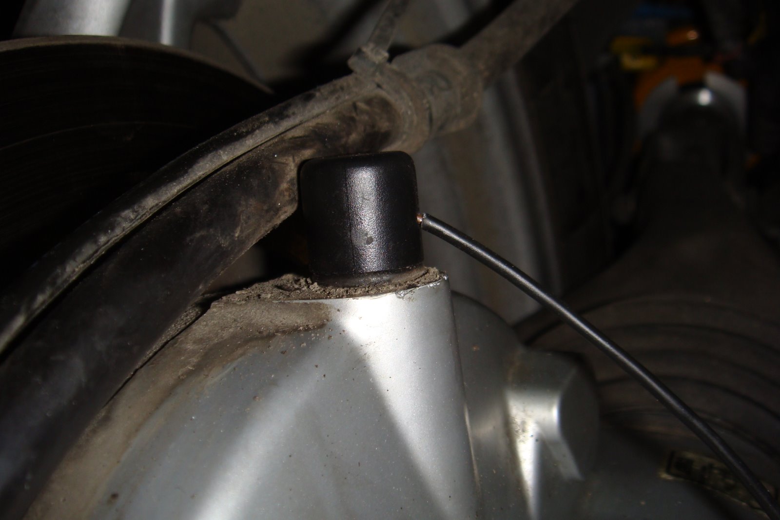
The mechanism rests on the bike frame. Here I was preparing the piece that bolts through the existing holes of the frame
bracket.

Here the second and final version is in place and in low position. This picture also shows my two rear fuse blocks which have nothing to do with the seat height adjuster. The Baehr box is the bike-to-bike radio. 
The next task was to make the base of the seat in such way that the lifting mechanism has a proper place to meet the seat.

I prepared a steel structure that is mounted on the bottom of the seat base.
And because there are two roller bearings on each side touching the seat base counter pieces, I had to make them in such way that the counter pieces can pivot. It is important as the angle of the seat changes during the lifting because I'm only lifting the tail of the seat. The pivot point is in the original place.

This is how the seat looks from underneath now.

Here the seat is in low position.

And here it is in high position.

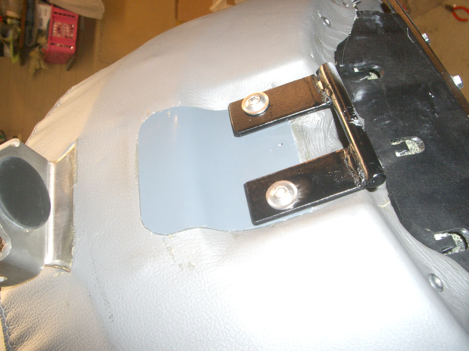
Making the seat adjustable that much resulted of course to other changes as well. The seat locking mechanism had to be altered.

I had to raise the seat lock mechanism to allow the seat to travel up and down the distance of 72 mm.
The next headache was the BakUp backrest which is normally fixed on the bike frame but now my seat was going to travel up and down...

Here is the original BakUp backrest. I cut off both ends of the curved bracket so that I could fasten it directly on the rider's seat. I drilled some five or six holes through the bracket and applied some epoxy glue and pop riveted the bracket right on the plastic base of the rider's seat. 

Unfortunately I did not document this phase of work properly but here you can see the back side of the rider's seat. I had to open the upholstery in order to fasten the bakup steel support right on the rear part of the rider's seat. The plastic piece is for protecting the leather from getting damaged by the seat lock mechanism.
Anyway, here is the backrest in place and it is fixed of the seat and thus moves up and down with the seat. The backrest has also a motor for adjusting it back and forth but that is again another story... 

I don't go into the electricals of the seat adjuster at this stage but if you are interested in how it was done give me a comment and I will shed some light on that subject, too.