Saturday, April 16, 2022

The gas cap modification

 OK guys, this is by no means my invention. The same instructions were found at the BMWLT.com forum already years ago but as it looks now at least some of the photos are lost and as I was recently asked about this modification by a fellow LT rider as he could not find it in internet so I figured I will add it here...

The modification concerns modifying the gas tank cap in such way that you don't necessarily need the ignition key every time you are filling the tank. Sometimes it is very irritating to first lock your handlebars and then take the ignition key off  simply for a gas fill. You can still lock the cap as before but also leave it unlocked.

So here is the way I was taught to do it:


You start the work by removing the gas cap cover. You can do it with the help of a small screwdriver.

Under the lid and lock cylinder there is a small spring, do not loose it!

Now you can remove the lock cylinder simply by lifting it out.

When you turn the key in the lock cylinder you can see the pin at the end of the cylinder go up and down. When the pin is up, you can open the gas cap. When it is down the cap just rotates and will not open. Normally the key comes out of the cylinder only when the pin is down. Our target is to modify the lock cylinder in such way that the key can come out in both pin positions.

Now turn the key in the cylinder so that the pin is in down position. Then wrap some tape around the pin to keep it in place as next we are going to take the lock cylinder in two parts. Look closer at the lower part of the cavity in the picture, there is a small metallic pin in the lower part of it. Push it in with a small screwdriver, drill bit or whatever fits in the cavity.

After you have pushed the little pin in you can pull the inner part (and the key) out from the cylinder. NOTE: keep the tape still around the cylinder although in this picture it is already removed. Also it is best you keep the key in the cylinder all the time.


The black "shelf" in the picture is the one that needs to be ground shorter.Make sure you shorten it from the direction of the arrow.


I used a Vise-grip to hold the the lock cylinder as it tends to get hot during grinding. Grind off about 60-70 % of the shelf. 

I also ground some plastic off the plastic outer cylinder.
The idea of the whole procedure is to grind enough material off both parts so that you can turn the key a full 180 degrees so that it can come out in both positions. Some people grind only from the plastic part in order to achieve the same result. You can do either way. Push in the key cylinder into the plastic once and test if the key turns enough, if not continue the grinding.

Here I was doing the grinding with a Dremel.

The final result is this. The plastic pin is out and the ignition key can be pulled out. Next simply reassemble you gas cap and now you can choose to lock it or leave unlocked. 


Saturday, April 10, 2021

Replacing the Gemel alarm/immobilizer/central lock unit

NOTE TO THE READER: 

THIS VERSION IS UPDATED ON MARCH 15TH 2021 AND THIS REPLACES ALL THE EARLIER VERSIONS. UPDATES ON THE SCHEMATICS WERE DONE AFTER THE FIRST RELEASE. 

UPDATE ON DEC 2TH 2022: A SIMPLER SCHEMATICS ADDED FOR THE PERSONS WHO DO NOT NEED BIKE FOUR WAY FLASHER TO REGISTER THE COMMANDS OF THE FOB.

This project started by accident in the spring of 2021. My winter was pretty busy with my regular work projects. (Yes, yes I am officially retired sice beginning of 2019, but what can you do when your old clients call and ask for assistance in their bakery projects...)

My original bucket list for this winter was really short. Just to replace the SmarTire tire pressure display unit in my upper dash. The famous LT-guru John Zeiler happened to have two new sets of the nowadays discontinued SmarTire motorcycle sets and he was kind enough to sell them to me. Replacing the display was an easy job and I had it done already in the beginning of November last year. 


Here I was still happy and putting the bike together just 20 minutes before I realized: "Houston, we have a problem..."

When putting the bike back together I realized that some of my added electrical gadgets did not work. And on top of this one of the bike's original 7,5 A fuses went off when I tried to connect my "master switch" for Ari's added electricals. 

Now this was not fun at all!

I just had to start stripping the bike all over again...

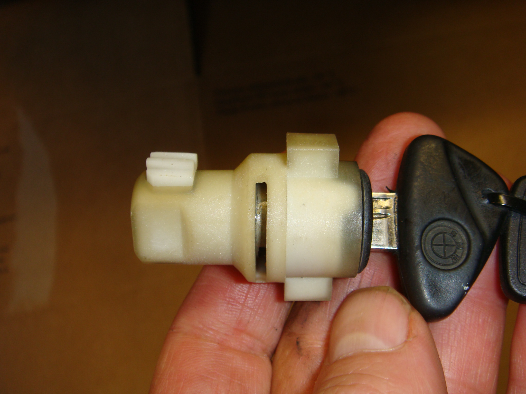
At some point I realized that my remote controller for the central locking and immobilizer was not working. I changed the battery in the fob but no success.

OK, looked like my Gemel (DWA5) unit was dead. ( About an hour later I realized the reason for this but that is another story.) The main thing was that my unit did not work. I was not concerned about the immobilizer or the alarm features since I have my own devices to make the life of a potential bike thief miserable. But I had lost the central locking!

So, following morning I sent email to our local BMW dealer and asked if they would have new units available. After two hours came the answer: No units in central warehouse in Sweden, nor any at the factory in Germany. But these units can still be ordered, price is 426 euros and delivery time is "several weeks". Ok, I could have tolerated the price but not the unknown delivery time.

My next task was then to look for instructions for removing the unit. There are plenty of them available when you just write "removing alarm K 1200 LT" in the Google. Here is one from Kirk Johnson.

BUT: When you remove the alarm unit from your facelift LT, you will also lose your central lock system! Not that it is one of the best ones with very limited range, but it still saves you from running around the bike and locking all the bags when parking the bike. So I wanted the central lock system must be maintained!

So I started figuring that there are still all the lock solenids in place so we just need a command unit for them. My first Google searches took me to the Chinese suppliers but this time I was not too keen in waiting 4-6 weeks for the package to arrive. Then I found this site from Finland.

I called them and checked that they indeed have them in stock and they said they will ship the next day. OK, the price was under 30 euros with postage. Reasonable. The gadget is still pobably produced in China (judging from the price.)

Here is one English speaking site which I found by typing the unit name "Bene 102A" in the Google search

While waiting for the unit to arrive I studied the schematics

I realized that it is the page 8 schematics of the manual that will work in LT. The polarity of feeding the solenoid / motors need to be changed when locking or unlocking the bags.

The original BMW unit also flashes the turn signals when you hit the fob. I consulted John Zeiler and he gave me some valuable hints so I was able to reproduce that feature with the Bene unit as well. But only with help of two additional relays plus one diode.  

In the following pages I try to give you as good advise as possible for carrying out a similar project. 

DISCLAIMER: You need some basic understanding about (bike) electrics and preferably ability to solder wires and of course you must know the anatomy of your LT so that you can remove the trunk and the cover underneath it. You also need two extra 12 V basic relays, one normally open (NO) and one normally closed (NC) type for the 4-way blinker function (optional). I use the Wehrle mini relays (to save space as I have about 50 of them spread all over the bike) but any regular 12 V auto relays work. Plus you need also one diode to isolate a two-way feed to the bike system. The tools that you need besides the soldering gun and solder are: Hot air blower for the shrink tubes, wire cutter, wire stripper, some zip ties, velcro for fastening the unit (or you can also use screws through the plastic). You can also use the "Abiko" type of connectors as well but there will be quite a few connections needed and some of them include up to five cables to be connected together. So I recommend soldering and covering the joints with shrink tube.

1. To start with follow the instructions of Kirk Johnsons video until he wants you to make the two jumps between pins #3 and 11 and the other jump between pins # 10 + 6 +2. STOP HERE, DONT MAKE THE JUMPS YET.

2. When you have the old BMW Gemel alarm unit in your hands, cut all the wires from it. You will need the connectors, so don't throw them away!
 You will need all the connectors except the one for the "tilt sensor" which you can throw avay. So you will have one 12-pin, connector, one 3-pin connector (bringing the power), and three 2-pin connetors (for the side cases and trunk solenoids). The glove box solenoid is powered through the 12-pin connector. 

3. Here is the new unit and its very long connecting cables straight from the package. Enough for seven installations at least...Note the fuse in the power cable and the antenna which hopefully improves the range of the fobs. 

This was my testing phase...


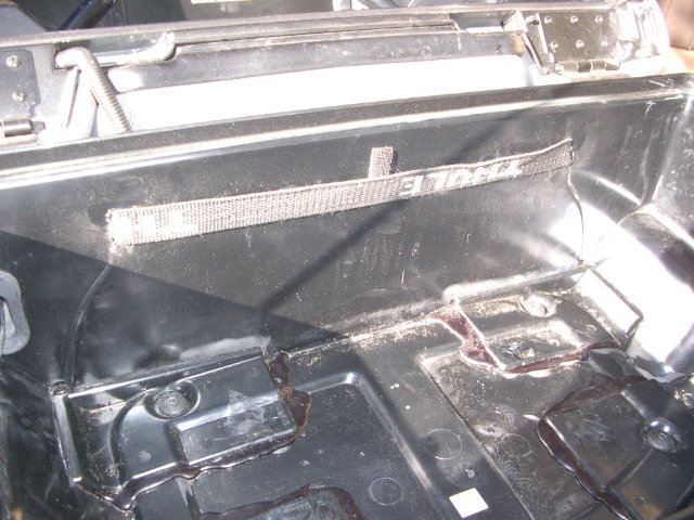
At first I was planning to use the original steel bracket but this compartment of my bike is so occupied by one air compressor and some 10 other relays and numerous connectors that I decided to throw the bracket away. There comes a double sided piece of tape with the Bene set but I preferred to use Velcro as the installation is less permanent with it.


4. Here the steel bracket is gone and the Bene is fastened with Velcro on the plastic surface of the rear compartment. You can see the three pin (power) connector next to the new unit. (Please ignore all the other relays and connectors is this and other pictures.)


I also covered the quite big opening above the Bene connector with Gorilla Tape. This is by no means a waterproof protection but will prevent regular dust & junk entering inside the unit. I was also considering sealing the whole unit waterproof with silicone, but since I never use pressure washer on my bike and the rear compartment stays relatively dry, I skipped that.

As you can see in some connections you need to collect a lot of wires. In the center there is the 3-pin connector and the continuous +12V connection is already done (with red, blue etc wires) and the grounding bundle is waiting for the solder and shrink tube to cover. In my earlier version the green switched power wire was unused but later I learned that this wire is needed. So do not cut it!


5. Here is the schematics of how the Bene 102 A is hooked up to bike connectors. I did some careful experimenting and found a safe way to enable the 4-way flashing feature when switching on or off the central lock. Thats why the 2 relays are added. If you don't want this feature, you can leave the relays out and also all the wiring plus diode that is connected to it plus the connection to pin #2 in the 12-pin connector. If you want to have a better printable schematics in PDF format send me an email and you will get one in return.

Some notes: 

The bike 3-pin connector brings continuous power, grounding and switched power. Even if the OEM alarm continuous 12V power feed is protected by a 15 A fuse (fuse #10 in bikes fuse box #2) I recommed that you use the 10 A fuse that comes with Bene AND install it under your rear seat instead of leaving it in the rear compartment. Much easier access to the fuse in case it ever blows...I stripped the bike original wire harness up to the bike fuse box level and connected the new fuse before the bike 3-pin connector (as shown in the schematics.) This was in order to avoid the double cables going back and forth to the rear compartment. I did this because I have about 15 other cables on the same route just to avoid the installation getting too tight.

Here are some other fuses as well under the pillion seat. The one for Bene is the cleanest looking... 

On the 12-pin connector you make two jumps: Pins # 3 and 11. The second jump between pins # 6 and 10. Pins 1 and 12 are used for bringing the power to the glove box solenoid. Pin # 2 brings power to the bike flasher unit and pin # 7 is used for bringing intermittent ground when doing the 4-way flashing with the Bene. But this same grounding has to be cut when the bike ignition is cut, otherwise the four way blinkers stay on continuously. (That is why the NC relay is needed.) With this installation there will be only three wires left over of this connector which you can just cut and leave them (isolated for security's sake) in place. 

When connecting the 2-pin connetors to the Bene unit, make sure they are all connected identically. The Bene blue cable hooks up to to the red/white wire of the solenoid cables and the Bene white cable hooks up to the brown/white wire of the solenoid cable. This way your new fob works logically. 

Here I was connecting the first additional (normally open NO) relay for enabling the 4-way blinkers. 


This picture shows how I connected the diode. In this picture the diode prevents the current flow from right to left but allows it from left to right.


Here the same diode and wire connections were covered with shrink tube


The completed installation. (The sticker on the Bene unit is scratched since I was looking for a hidden screw as wanted to open the unit and see what it had eaten. There was no screw. The unit cover opens from the bottom side by simply spreading it open with a thin screwdriver.)


Here the rear compartment cover was going back in place. You can also see my little Thomas air compressor which is fastened on the lid. Luckily the Euro bikes do not have the famous canister that the US bikes have filling this otherwise very useful compartment!


All done! Just the top box to be installed...(If you are wondering the brackets, they ar for relocating the trunk additional 30 mm backwards from the factory rearmost position. There is a separate story about it in this blog.)


And here is finally the proof of how it works, One flash is locked, two flashes unlocked!


Update on Dec 2th 2022:
A simpler schematics if you do not want to have the 4-way flashers to operate and register the commands of the remote control fob.


Tuesday, August 18, 2020

Strapping stuff on the bike and strapping the bike itself

As the "LT" is an abbreviation from "Light Truck" it is obvious that you occasionally end up hauling some extra stuff on your bike and then it would of course be nice if this is somehow planned in advance.

My first need for this came already during my first riding season back in 2005 when I was commuting to my that time office some 55 km away from home. Normally I had my work briefcase in the trunk where it fit perfectly. But quite often I got a message from my dear wife "why don't you bring some milk/yoghurt/cheese/whatever on your way home". Sometimes the shopping list was so long that I could not fit the stuff in the side bags. Especially when the side bags were already packed with bread since I happened to be working in a large bakery where fresh bread was regularly available...
Anyway, as a result of this the easiest way to arrange some more space for the odd milk and yoghurt cartons was to take my work case out from the trunk and tie it on the rear seat. 
So I made permanent straps that I can take out in seconds and fasten all kinds of things on the rear seat.


Here was my first strap. I simply cut long vertical openings in the front wall of the trunk to fit a long enough strap that goes through them. (Note: the trunk liner is of course removed before making the holes!)

Here the strap ends come out.


And here the strap ends are rolled in out of the way.


And here my work bag was tied on the rear seat. 


Soon I realized that I needed also tie points from other direction for some different kind of bags. Using the side case handles would have been the straight forward way to go but this would not work if you need to have access to the side cases as well.

For my USA trip back in 2006 I was going to have a RKA rack bag permanently tied down on the rear seat. I was saving the trunk rack for some ad hoc tie down needs.

So I simply took a proper length of strap and fastened it under the rear seat with screws. I made loops in both ends of the strap.
...like this. These loops are normally out of way and will not bother closing the side bags.


And my RKA bag stayed in place like this. In the bag I kept my larger camera, and large thermos bottles with ice and Kool-Aid. 

The straps that I used on this USA trip were long enough so that the ends would reach down inside the side case. This way stealing the case would need the straps to be cut at first. Luckily our that time trip took us to no such neighborhoods where even worrying about this was no issue.


Sometimes I need a different shape of bag on the rear seat:

This is a Chicane rack bag for LT.(Unfortunately no longer available other than used ones occasionally on certain forums.)


I sewed loops in the bottom of the Chicane bag and through them I can lock the bag on the rear seat when I'm riding solo. 


...like this. These straps with plastic locks are taken from old bicycle helmets.


Then how to strap the bike on trailers, ferries, trains etc...?

Back in 2006 when me and my travel buddy Jouko were preparing our bikes for their flights over the Atlantic (Frankfurt-Calgary and Toronto-Frankfurt) we found this set mady by German Wüdo. It was made specially for an LT. (Later we learned that when a bike is tied down on an air cargo pallet they only use their own air cargo rated straps and belts and they could care less about our own straps.)


Anyway, this is the Wüdo piece that goes between the front forks.

Here the piece is upside down. The cavity in the middle occupies the plastic covered center nut between the forks.


...like this. As I said the guys in the air cargo we not interested in using this and during the past 15 years I have needed this only once when I hauled the bike in wintertime half stripped on a trailer to have the brake lines changed.

These also came with the Wüdo set. As you can see from the scratches these have been used a lot. Every time on a ferry I use these for keeping the bike in place. 

Since the above described Wüdo sets are probably no longer available or if they are,they are quite pricey, I have developed a simple replacement for the side fixing point. Here is the recipe:
1. Take out the upper bolt that holds the pillion foot peg plate.

2. Take a 8 mm (stainless steel) ring bolt and approriate amount of 8 mm washers. (You can get these at least from a boat store in case your local hardware store does not carry these.)  

3.Replace the original allen bolt with this new ring bolt.
4. When you need to strap your bike down, place these hooks (fire safety hooks....? in English) on your ring bolt so now you have space for heavier straps.
5.You can leave your ring bolts in place permanently.

These parts were purchased from the boat department of a Swedish hardware chain "Biltema". In case some of you have this store within reach.


Monday, August 17, 2020

The hitch and what is hanging on it

 Already back in 2005-2006 I started planning some kind of additional luggage rack for our longer trips. So started searching for some trailer hitches as I figured that is a good starting point for fixing the luggage rack on the bike. I had seen them on GoldWings but at that time there were none available for LT's.

Somehow I spotted an ad either on eBay or BMWLT.com classified about a used Dauntless LT trailer hitch for sale. The seller was kind enough to ship it all the way to Finland and to my pleased surprise this hitch was already equipped with a square receiver tube instead of the regular hitch ball. At that time I was not in favor of purchasing a trailer.


Here is the hitch itself. The previous owner had installed a plastic mud flap extension on the Dauntless tubes and as this seemed to work well with preventing the water from spraying all over I left this in place.The receiving tubes (with plastic caps) are already installed in the bike. The  power socket can be seen on the right. Unfortunately I don't have a picture of the set before installation but if you make a Google search with "dmc trailer hitch K 1200 LT" you will get plenty of pictures. You can also try with the older brand name "dauntless trailer hitch K 1200 LT"


Here is a good side view of my Dauntless (later DMC) hitch and receiver in place. That summer I also had the Remus exhaust pipe for 2 months. Until I got fed up with the rumble it made at typical touring speeds of 100 km/h...
What I like with this Dauntless /DMC hitch is that it is easy to remove when not used and leaves the bike looks practically intact.

As in every project, proper planning is half of the success. So I started making some 3D-sketches of my rack with my AutoCad...


This was my final design of the rack. The bike parts (rear tire, exhaust, trunk) are pretty simple as you can see...;-)


Here was the frame.


This described the Delsey suitcase I was planning to mount on the rack. Since the weight of the bag could be up to 20 kg I needed the cables that would give support from the top as well.


And here was the ready version 1.0. (I later replaced the cable fastening with different system so that I could avoid using the spreading bar.) I added an extra brake light and side marker lights to the rack since the power for these was easy to get from the power socket that came with the hitch.
The rack frame was not built by me but by an associate stainless steel professionals who build bakery ovens as their daily business.

I even had a 12 V fridge/cooler that would fit on the rack. To be honest I never really used it though...


Later I modified the upper fastening points in such way that I could avoid using the "spreading bar" for the cables as this was pretty much on the way of removing and putting in place of the Delsey bag.

I designed a "V-shaped" steel bar out of a 5 x 30 mm flat steel.
...like this, I made 10 mm threaded holes and welded U-shaped hooks at the ends of the V-bar.


The V-bar is fastened of these steel bars that were originally made for relocating the trunk 30 mm further backwards from the factory rear position.  You can read that story here

And here is a close-up of how the bar is fastened on the bike.


And this is what the hitch rack looks like from the side. I had a black vinyl cover / hood made for the Delsey flight bag. This protects the bag from rain etc. BTW, when I had the Remus exhaust (without the catalytic converter) for the one summer, it contaminated the bag with very heavy exhaust fumes smell. When I returned back to the OEM exhaust this problem was mostly gone.

And this is from another angle. The extra weight in the tail can be noticed but it is not too bad. About the same as my Uni-Go is giving...

Below some detail pics of the cable supports.

The rack side fastening points are "telescopes"...


...like this. They can be pulled out in case a wider bag must be fitted on the rack.


I used the stuff from a boat shop for my cable fastening and tightening,


This is the top fastening (bad photo, sorry...)

This story continues later with the Uni-Go as I finally decided to purchase one back in 2010.